Introduction
RaspberryPi2, the popular Open Source Hardware Board recently launched this February, 2015 year operating out of cool, different Linux based flavors like Debian, Fedora, Archlinux ARM, Android and additionally Windows operating system, Windows10, improves power packed performance derieved from a 900 MHz quad-core ARM Cortex-A7, Broadcom BCM2836 SoC, with 1GB SDRAM, HDMI, GPIOs, I2C, SPI, UART, I2S and other mindblowing stuff, like support for Camera, Display, Shield boards et al. Fig. below shows the location of the Connectors and Expansion Headers of Rpi2.
 |
| Fig.1 Location of expansion header, connectors and main ICs on Raspberry Pi 2 model B |
Now,coming to nRF24L01+, the nRF24L01+ is a single chip 2.4GHz transceiver with an embedded baseband protocol engine (Enhanced ShockBurst™), suitable for ultra low power wireless applications. The nRF24L01+ is designed for operation in the world wide ISM frequency band at 2.400 - 2.4835GHz. To design a radio system with the nRF24L01+, you simply need an MCU (microcontroller) and a few external passive components.
You can operate and configure the nRF24L01+ through a Serial Peripheral Interface (SPI). The register map, which is accessible through the SPI, contains all configuration registers in the nRF24L01+ and is accessible in all operation modes of the chip.
The embedded baseband protocol engine (Enhanced ShockBurst™) is based on packet communication and supports various modes from manual operation to advanced autonomous protocol operation. Internal FIFOs ensure a smooth data flow between the radio front end and the system’s MCU. Enhanced ShockBurst™ reduces system cost by handling all the high speed link layer operations.
The radio front end uses GFSK modulation. It has user configurable parameters like frequency channel, output power and air data rate. nRF24L01+ supports an air data rate of 250 kbps, 1 Mbps and 2Mbps. The high air data rate combined with two power saving modes make the nRF24L01+ very suitable for ultra low power designs.
Having two or more RaspberryPi2/RaspberryPi/Arduinos be able to communicate with each other wirelessly over a distance opens lots of possibilities:
•Remote sensors for temperature, pressure, alarms, much more
•Robot control and monitoring from 50 feet to 2000 feet distances
•Remote control and monitoring of nearby or neighborhood buildings
•Autonomous vehicles of all kinds
•Remote sensors for temperature, pressure, alarms, much more
•Robot control and monitoring from 50 feet to 2000 feet distances
•Remote control and monitoring of nearby or neighborhood buildings
•Autonomous vehicles of all kinds
nRF24L01+ is drop-in compatible with nRF24L01 and on-air compatible with nRF2401A, nRF2402, nRF24E1 and nRF24E2. Intermodulation and wideband blocking values in nRF24L01+ are much improved in comparison to the nRF24L01 and the addition of internal filtering to nRF24L01+ has improved the margins for meeting RF regulatory standards.
Internal voltage regulators ensure a high Power Supply Rejection Ratio (PSRR) and a wide power supply range.
The nRF24L01+ Module.
The nRF24L01+ Module, that we have considered here comes from Amazon, for less than 100 INR,(< 1.58$). These are a series of 2.4 GHz Radio modules that are all based on the Nordic Semiconductor nRF24L01+ chip. (Details) The Nordic nRF24L01+ integrates a complete 2.4GHz RF transceiver, RF synthesizer, and baseband logic including the Enhanced ShockBurst™ hardware protocol accelerator supporting a high-speed SPI interface for the application controller.
 |
| Fig 2. nRF24L01+ Module |
These transceivers use the 2.4 GHz unlicensed band like many WiFi routers, some cordless phones etc.
Transceivers like these both send and receive data in 'packets' of several bytes at a time. There is built-in error correction and resending, and it is possible to have one unit communicate with up to 6 other similar units at the same time.
They all use the same pinout as shown in the below diagram, which is the Top view,
 |
| Fig 3. Top View pinout of nRF24L01+ Module |
Here are the details of the BottomView Pinout of nRF24L01+ Module and connections to RaspberryPi and RaspberryPi2:
 |
| Fig 4. Bottom View Pinout of nRF24L01 Module and corresponding Pin mapping with Rpi2 and Rpi Model B |
NOTE! Power Problems:
Many times we have had trouble getting the nRF24L01 modules to work. Many times the problem is that the 3.3V Power to the module does not have enough current capability, or current surges cause problems. Here is one suggestion:
• Solder a 3.3 uF to 10 uF (MicroFarad) capacitor directly on the module from +3.3V to Gnd (Watch + and - !)This is especially important if you are connecting the other pins like CSN, CE, MISO, MOSI of the module with jumper wires. I soldered a 4.7uF, Coupling or a Bypass Capacitor between Pins 1(-ve of Cap) and 2(+ve of Cap). Here is what i connected between Vcc and Gnd. ( For more Info on Capacitive Coupling, please try: http://electronicsclub.info/capacitance.htm#coupling )
Configuring nRF24L01+.
To configure the nRF24L01+, we have to refer the Product Specification document, "nRF24L01P_Product_Specification_1_0.pdf", Chapter 6, Pg. no. 21, talks about Radio Control, which is required to be understood, in order to control the Radio. You can configure the nRF24L01+ in power down, standby, RX or TX mode. When the VDD reaches 1.9V or higher nRF24L01+ enters the Power on reset state where it remains in reset until entering the Power Down mode. The below state diagram(Pg. no. 22) illustrates, the relationship between the states, with changes in control Signals, like CE, and PRIM_RX, which are required to control the Radio Transfer operations.

Power Down Mode
In power down mode nRF24L01+ is disabled using minimal current consumption. All register values available are maintained and the SPI is kept active, enabling change of configuration and the uploading/downloading of data registers. Power down mode is entered by setting the PWR_UP bit in the CONFIG register low.
Standby Modes
Standby-I mode - By setting the PWR_UP bit in the CONFIG register to 1, the device enters standby-I mode. Standby-I mode is used to minimize average current consumption while maintaining short start up times. In this mode only part of the crystal oscillator is active. Change to active modes only happens if CE is set HIGH and when CE is set LOW, the nRF24L01 returns to standby-I mode from both the TX and RX modes.
Standby-II mode - In standby-II mode extra clock buffers are active and more current is used compared to standby-I mode.nRF24L01+ enters standby-II mode if CE is held high on a PTX device with an empty TX FIFO. If a new packet is uploaded to the TX FIFO, the PLL immediately starts and the packet is transmitted after the normal PLL settling delay (130µs).
RX mode
The RX mode is an active mode where the nRF24L01+ radio is used as a receiver. To enter this mode, the nRF24L01+ must have the PWR_UP bit, PRIM_RX bit and the CE pin set high. In RX mode the receiver demodulates the signals from the RF channel, constantly presenting the demodulated data to the baseband protocol engine. The baseband protocol engine constantly searches for a valid packet. If a valid packet is found (by a matching address and a valid CRC) the payload of the packet is presented in a vacant slot in the RX FIFOs. If the RX FIFOs are full, the received packet is discarded. The nRF24L01+ remains in RX mode until the MCU configures it to standby-I mode or power down mode.
However, if the automatic protocol features (Enhanced ShockBurst™) in the baseband protocol engine are enabled, the nRF24L01+ can enter other modes in order to execute the protocol.
In RX mode a Received Power Detector (RPD) signal is available. The RPD is a signal that is set high when a RF signal higher than -64 dBm is detected inside the receiving frequency channel. The internal RPD signal is filtered before presented to the RPD register. The RF signal must be present for at least 40µs before the RPD is set high.
TX mode
The TX mode is an active mode for transmitting packets. To enter this mode, the nRF24L01+ must have the PWR_UP bit set high, PRIM_RX bit set low, a payload in the TX FIFO and a high pulse on the CE for more than 10µs. The nRF24L01+ stays in TX mode until it finishes transmitting a packet. If CE = 0, nRF24L01+ returns to standby-I mode.
If CE = 1, the status of the TX FIFO determines the next action.
If the TX FIFO is not empty the nRF24L01+ remains in TX mode and transmits the next packet. If the TX FIFO is empty the nRF24L01+ goes into standby-II mode. The nRF24L01+ transmitter PLL operates in open loop when in TX mode. It is important never to keep the nRF24L01+ in TX mode for more than 4ms at a time. If the Enhanced ShockBurst™ features are enabled, nRF24L01+ is never in TX mode longer than 4ms.

Few other parameters to be looked into are the Air data rate, RF channel frequency, PA control.
Air data rate
The air data rate is the modulated signaling rate the nRF24L01+ uses when transmitting and receiving
data. It can be 250kbps, 1Mbps or 2Mbps. Using lower air data rate gives better receiver sensitivity than higher air data rate. But, high air data rate gives lower average current consumption and reduced probability of on-air collisions.
The air data rate is set by the RF_DR bit in the RF_SETUP register. A transmitter and a receiver must be programmed with the same air data rate to communicate with each other. nRF24L01+ is fully compatible with nRF24L01. For compatibility with nRF2401A, nRF2402, nRF24E1, and nRF24E2 the air data rate must be set to 250kbps or 1Mbps.
RF channel frequency
The RF channel frequency determines the center of the channel used by the nRF24L01+. The channel
occupies a bandwidth of less than 1MHz at 250kbps and 1Mbps and a bandwidth of less than 2MHz at 2Mbps. nRF24L01+ can operate on frequencies from 2.400GHz to 2.525GHz. The programming resolution of the RF channel frequency setting is 1MHz.
At 2Mbps the channel occupies a bandwidth wider than the resolution of the RF channel frequency setting. To ensure non-overlapping channels in 2Mbps mode, the channel spacing must be 2MHz or more. At 1Mbps and 250kbps the channel bandwidth is the same or lower than the resolution of the RF frequency. The RF channel frequency is set by the RF_CH register according to the following formula:
F0= 2400 + RF_CH [MHz]
You must program a transmitter and a receiver with the same RF channel frequency to communicate with each other.
PA control
The PA (Power Amplifier) control is used to set the output power from the nRF24L01+ power amplifier. In TX mode PA control has four programmable steps, see Table below. The PA control is set by the RF_PWR bits in the RF_SETUP register.
 |
| Fig 5. Table depicting the RF Power Amplifier output power setting bits in RF_PWR Register. |
MultiCeiver.
Section 7.6, pg. no. 39 explains the MultiCeiver feature, which is a feature used in TX/RX mode that contains a set of six parallel data pipes with unique addresses. A data pipe is a logical channel in the physical RF channel. Each data pipe has its own physical address (data pipe address) decoding in the nRF24L01+.
nRF24L01+ configured as PRX (primary receiver) can receive data addressed to six different data pipes in one frequency channel as shown in Fig below. Each data pipe has its own unique address and can be configured for individual behavior.
Up to six nRF24L01+s configured as PTX can communicate with one nRF24L01+ configured as a PRX. Alldata pipe addresses are searched for simultaneously. Only one data pipe can receive a packet at a time. All data pipes can perform Enhanced ShockBurst™ functionality.
Up to six nRF24L01+s configured as PTX can communicate with one nRF24L01+ configured as a PRX. Alldata pipe addresses are searched for simultaneously. Only one data pipe can receive a packet at a time. All data pipes can perform Enhanced ShockBurst™ functionality.
The following settings are common to all data pipes:
• CRC enabled/disabled (CRC always enabled when Enhanced ShockBurst™ is enabled)
• CRC encoding scheme
• RX address width
• Frequency channel
• Air data rate
The data pipes are enabled with the bits in the EN_RXADDR register.
By default only data pipe 0 and 1 are enabled.
Each data pipe address is configured in the RX_ADDR_PX registers.
Note: Always ensure that none of the data pipes have the same address.
Each pipe can have up to a 5 byte configurable address. Data pipe 0 has a unique 5 byte address. Data
pipes 1-5 share the four most significant address bytes. The LSByte must be unique for all six pipes. Figure below is an example of how data pipes 0-5 are addressed.
pipes 1-5 share the four most significant address bytes. The LSByte must be unique for all six pipes. Figure below is an example of how data pipes 0-5 are addressed.
 |
| Fig 6. Data Pipe pairs to be adressed for Rx/Tx, Transmit and Recieve Data Pipes will be assigned unique adresses, Pipe 0 and Pipe 1 are enabled by default. |
The PRX, using MultiCeiver, receives packets from more than one PTX. To ensure that the ACK packet from the PRX is transmitted to the correct PTX, the PRX takes the data pipe address where it received the packet and uses it as the TX address when transmitting the ACK packet. Figure below, is an example of an address configuration for the PRX and PTX. On the PRX the RX_ADDR_Pn, defined as the pipe address, must be unique . On the PTX the TX_ADDR must be the same as the
RX_ADDR_P0 and as the pipe address for the designated pipe. Only when a data pipe receives a complete packet can other data pipes begin to receive data .
| Fig 7. Example of data pipe addressing in MultiCeiver |
As, shown in the above example, the Central Node, PRX is assigned with the following Rx Data Pipe addresses,(there will also be corresponding Tx address assigned to the Central Node, but we will not be looking into that), the Rx addresses of the Rx/Tx DataPipe assigned to the Central Node are:
Addr Data Pipe 0 (PRX_ADDR_P0): 0x7878787878
Addr Data Pipe 1 (PRX_ADDR_P1): 0xB3B4B5B6F1
Addr Data Pipe 2 (PRX_ADDR_P2): 0xB3B4B5B6CD
Addr Data Pipe 3 (PRX_ADDR_P3): 0xB3B4B5B6A3
Addr Data Pipe 4 (PRX_ADDR_P4): 0xB3B4B5B60F
Addr Data Pipe 5 (PRX_ADDR_P5): 0xB3B4B5B605
Now, say there 6 Transmitters having nRF24L01+ modules, PTx1, PTx2, PTx3, PTx4, PTx5 and PTx6s. Say, for the time, we are using the DataPipe 0, in each of these Transmitting modules and we have to set Tx address of the Rx/Tx Data Pipe with the correct Rx unique address of the PRX DataPipe,so that the DataPipe_X recieves the data destined from corresponding PTx. No Tx addresses should be same among the PTx modules. The user has to take care of that aspect, in which case incorrect operation of logic can happen. The following way, the trasmission operation will take place between the 6 PTx Nodes and the PRx central node:
PTX1 (PTX1_ADDR_P1) : 0xB3B4B5B6F1 ==> Data Pipe 1 (PRX_ADDR_P1): 0xB3B4B5B6F1
PTX2 (PTX2_ADDR_P2) : 0xB3B4B5B6CD ==> Data Pipe 2 (PRX_ADDR_P2): 0xB3B4B5B6CD
PTX3 (PTX3_ADDR_P3) : 0xB3B4B5B6A3 ==> Data Pipe 3 (PRX_ADDR_P3): 0xB3B4B5B6A3
PTX4 (PTX4_ADDR_P4) : 0xB3B4B5B60F ==> Data Pipe 4 (PRX_ADDR_P4): 0xB3B4B5B60F
PTX5 (PTX5_ADDR_P5) : 0xB3B4B5B605 ==> Data Pipe 5 (PRX_ADDR_P5): 0xB3B4B5B605
PTX6 (PTX6_ADDR_P6) : 0x7878787878 ==> Data Pipe 0 (PRX_ADDR_P0): 0x7878787878
SPI Commands for accessing and controlling nRF24L01+ Registers and for Read/Write.
Section 8.3 of nRF24L01P_Product_Specification_1_0.pdf, describes the SPI commands and the required Timing. The SPI commands are shown in Table below. Every new command must be started by a high to low transition on CSN. The STATUS register is serially shifted out on the MISO pin simultaneously to the SPI command word shifting to the MOSI pin.
The serial shifting SPI commands is in the following format:
<Command word: MSBit to LSBit (one byte)>
<Data bytes: LSByte to MSByte, MSBit in each byte first>
 |
| Fig. 8 SPI Commands for accessing Status Registers, and Read/Write Operation |
SPI operation and timing is shown in Fig. below. nRF24L01+ must be in a standby or power down mode before writing to the configuration registers.
 |
| Fig. 9 SPI Command timing diagram for Read/Write and reading configuration registers. |
Setting up the RaspberryPi's.
This section describes the setup of the nRF24L01+ Modules with RaspberryPis. Two RaspberryPi have been used here. Two nRF24l01+ Modules have been used. One nRF24L01+ Module has been interfaced with a RaspberryPi, and the other has been interfaced with one RaspberryPi2. Thus, i am using the Module nRF24L01+ to communicate between two RaspberryPis wirelessly.
The 1st Module nRF24L01+ is connected to RaspberryPi, Model B. Please see, the Fritzing diagram given below:
 |
| Fig. 10 1st module, nRF24L01+ interfaced to RaspberryPi, Model B |
The second nRF24L01+ Module has been interfaced with a RaspberryPi2, Model B. Later, we will see, how we are using one RaspberryPi as Transmitter and the other RaspberryPi2 as Reciever, using nRF24L01+. The below Fritzing diagram shows the connection of nRF24L01+ Module with RaspberryPi2.
 |
| Fig. 11 2nd Module, nRF24L01+ interfaced with RaspberryPi2 |
The Fritzing project for RaspberryPi2 interfaced with nRF24L01+ can be found and downloaded from the link below, where i have shared the .fzz, file. Download latest cool Release of Fritzing Tool from the following link(http://fritzing.org/download/).
https://drive.google.com/file/d/0B6Cu_2GN5atpTjZUNzhlNzdJODQ/view?usp=sharing
After, setting up the connections, we will now look into the nRF24L01 Application program and the Libraries required to configure SPI, nRF24L01+ Routines on RaspberryPi and RaspberryPi2. Firstly, we need to configure the GPIOs and SPI pins to enable the /dev/spidev0.0 and /dev/spidev1.0 device Node for SPI, spi_bcm2708 Driver.
A wonderful Library has been provided towards this end by Mike, which works well with both RaspberryPi and RaspberryPi2. My concern while using it, was if it would work with RaspberryPi2. The latest version, of the library, bcm2835-1.46.tar.gz works well with both RaspberryPi and RaspberryPi2. The following version can be downloaded from the link below:
http://www.airspayce.com/mikem/bcm2835/bcm2835-1.46.tar.gz
or users can access my shared drive, to download it, of the above link is'nt working.
https://drive.google.com/open?id=0B6Cu_2GN5atpWmVxX2VvYjJTZVU
After, that follow the below instructions to install the library to your RaspberryPi and RaspberryPi2.
# download the latest version of the library, say bcm2835-1.xx.tar.gz, then:
tar zxvf bcm2835-1.xx.tar.gz cd bcm2835-1.xx
./configure
make
sudo make check
sudo make install
NOTE: Raspberry Pi 2 (RPI2)
For this library to work correctly on RPI2, you MUST have the device tree support enabled in the kernel.
You should also ensure you are using the latest version of Linux. The library has been tested on RPI2 with
2015-02-16-raspbian-wheezy and ArchLinuxARM-rpi-2 as of 2015-03-29.
When device tree suport is enabled, the file /proc/device-tree/soc/ranges will appear in the file system,
and the bcm2835 module relies on its presence to correctly run on RPI2 (it is optional for RPI1). Without
device tree support enabled and the presence of this file, it will not work on RPI2.
To enable device tree support:
sudo raspi-config under Advanced Options - enable Device Tree and Reboot.
Library Sources and Applications.
Next, we will now look into the Library sources and the Application, use the below nRF24L01+ library, that i have shared below(This is meant for Rpi2, hence download or copy it to your Rpi2 Root File system):
https://drive.google.com/open?id=0B6Cu_2GN5atpUlA3QjU5aW9iTFk
Firstly, unzip this library on Rpi2 and install this library, as shown in the screen shot below:
 |
| Fig. 12 Installing the nRF24L01+ Library on RaspberryPi2 |
I will briefly outline the steps involved in installing and building the library.
After, extracting the nRF24L01+ Library, untar the 'RF24.tar' and go inside 'RF24' folder,
- First, clean the sources, #make clean.
- After, that do, #make all, and build all the sources.
- After, that install the sources, using #make install, which will install the libraries librf24-bcm.so.
- After, that go inside the folder, 'examples_RPi', and build the applications for RaspberryPi2, that we are going to see just now, using #make all.
The Library allows users to override the BCM2835 Driver for SPIDEV, and use some other customized driver or some other platform, like BeagleBone Black by using the using the command during 'make all' and 'make install',
#sudo make all -B RF24_SPIDEV=1
#sudo make install -B RF24_SPIDEV=1
This is so, because if we look at the Makefile, present inside RF24 directory,as shown below:
 |
| Fig. 13 RF24_SPIDEV Flag used to override the usage of BCM2835 Driver, spidev0.0/spidev1.0. |
As, shown above, in the Make Rule, ifeq "$(RF24_SPIDEV)" "1", then RPI variable is assigned '0'. Later below we are checking if this variable 'RPI' is set or not, based on which the Driver directory is picked inside the 'RF24/utility',
ifeq "$(RF24_MRAA)" "1" // For MRAA Board ?
........
< Pick the Driver for MRAA Board>
....
else ifeq "$(RPI)" "1" // Else for Rpi Board
.......
< Pick the Driver for Rpi Board>
....
else // Else for BBB(BeagleBone Black board
.......
< Pick the Driver for BBB Board>
....
endif
Now, that we have built and installed the Libraries for SPI and nRF24L01+, its time to check the correctness of our Library. Before that, i would like to point out the minor changes and adjustments that had to be done in the Library sources. The CSN signal needs to be pulled HIGH after being pulled LOW, in RF24.cpp, as shown below(SEE: Timing Diagram, Fig. 9, CSN signal is Pulled LOW during the Transfer and Commands, and Pulled HIGH, after Transfer is over):
 |
| Fig. 14 Making CSN Signal HIGH, after pulling it LOW, in the Library file, RF24.cpp, required otherwise NRF24L01+ Resets after 1st Transfer. |
Similarly, in other functions, the CSN Signal has to be pulled HIGH, after pulled down LOW, in RF24.cpp. The file, RF24.cpp is present inside /RF24 Directory.
uint8_t RF24::read_register(uint8_t reg, uint8_t* buf, uint8_t len)
{
uint8_t status;
csn(LOW);
status = SPI.transfer( R_REGISTER | ( REGISTER_MASK & reg ) );
while ( len-- )
*buf++ = SPI.transfer(0xff);
csn(HIGH);
return status;
}
uint8_t RF24::write_register(uint8_t reg, const uint8_t* buf, uint8_t len)
{
uint8_t status;
csn(LOW);
status = SPI.transfer( W_REGISTER | ( REGISTER_MASK & reg ) );
while ( len-- )
SPI.transfer(*buf++);
csn(HIGH);
return status;
}
Please refer the file RF24.cpp inside RF24 directory of the shared library sources zip, or refer the RF24.cpp file shared in my Google Drive path below:
https://drive.google.com/file/d/0B6Cu_2GN5atpS3pySmZwX0NwRjQ/view?usp=sharing
Install the same Library,that i have shared above on RaspberryPi also. In the same way, and fashion, as described above. Thus, now we have installed the nRF24L01+ Library on RaspberryPi and RaspberryPi2.
Now, we shall look into making use of our Library. For, this we don't need to look any further. Examples aplenty are provided for RaspberryPi inside the folder, 'RF24/examples_RPi'. If, one needs to build it separately, one can do so, using #make all inside 'examples_RPi' directory.
The example that we will consider here is 'pingpair_dyn.cpp', present in '/RF24/examples_RPi' directory. What this Application does is, it Transfers and Recieves Payloads of varying(Dynamic) sizes. It sets up Radio Pipe addresses, to set up two Nodes/Pipes, one for Transmitting and the other for Receiving. The Application asks user to sets up the Role, as Transmitter or Receiver, and Transmits or Receives a chain of characters every time, in a continuous 'while' loop.
In the 'pingpair_dyn.cpp' application, we will see what configurations and pin mapping we are doing. When we are running this Application on RaspberryPi2, we will use this Pin mapping, as shown in the fig. below. The first thing, in this Application is the constructor call to create the RF24 'radio' object. This Initializes the SPI Pins, the SPI Mode, the SPI Speed and signal polarity and in accordance with the H/W SPI spidev0.0/spidev1.0 BCM2835 Driver. This is very very important. The Pin settings for the setup for Application 'pingpair_dyn.cpp' on Rpi2 should be,
// Setup for GPIO 15 CE and CE0 CSN with SPI Speed @ 8Mhz
RF24 radio(RPI_V2_GPIO_P1_15, RPI_V2_GPIO_P1_24, BCM2835_SPI_SPEED_8MHZ);
 |
| Fig. 15 For RPi2, RF24 Radio object constructor to map the Pins used to the Hardware SPI driver and initialize the settings. |
In RaspberryPi1, RaspberryPi Model B, we will have the below setup, for the Application 'pingpair_dyn.cpp'. GPIO22 Pin will be setup as CE and CE0 Pin will be setup as CSN.
// Setup for GPIO 22 CE and CE0 CSN with SPI Speed @ 4Mhz
RF24 radio(RPI_V2_GPIO_P1_22, BCM2835_SPI_CS0, BCM2835_SPI_SPEED_4MHZ);
Please see the fig. below for the RF24 radio object constructor initialization for RaspberryPi, Model B(RPi1).
 |
| Fig. 16 For RaspberryPi, Model B, RF24 Radio object constructor to map the Pins used to the Hardware SPI driver and initialize the settings. |
Now, for some configuration Register setting, i have disabled the CRC, as shown in the lines below, and since the two Raspberry Pis are communicating, thus the Transmitting Pipe Address of one RaspberryPi should be the same used by the Receiving Pipe of the other RaspberryPi.
 |
| Fig. 17 CRC Checking has been disabled for the Application, and Pipe[0] and Pipe[1] are used interchangeably as Transmitting and corresponding Receiving Pipe. |
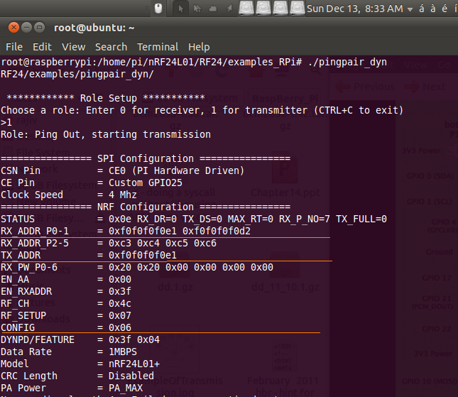
So, the Configuration looks basically like this, if we run the Application, 'pingpair_dyn' on RaspberryPi2
#./pingpair_dyn
 |
| Fig. 18 nRF24L01+ Configuration Register values and SPI settings for RaspberryPi2. |
Similarly, for RaspberryPi1(RaspeberryPi, Model B), the configuration looks something like this, as shown below in Fig 19. The Library and the Packages will be installed the same way, as described above, for RaspberryPi too. The same packages and library will be used for RaspberryPi, Model B(nRF24L01+ and BCM2835 Library). The only difference will be in the Application, 'pingpair_dyn.cpp' file. For, more Reference, please refer to the attached file, 'pingpair_dyn.cpp'. Replace the file 'pingpair_dyn.cpp' in '/examples_Rpi' directory with this file given in the link below on RaspberryPi, Model B.
https://drive.google.com/open?id=0B6Cu_2GN5atpbDZQcUU0bUZiekE
 |
| Fig. 20 nRF24L01+ Configuration Register values and SPI Settings for RaspberryPi, Model B. |
One thing to notice here are the values of the Register. The value of the CONFIG Register for RaspberryPi2 is 0x07, while for RaspberryPi, Model B, it is 0x06. If, we refer the Datasheet, "nRF24L01P_Product_Specification_1_0.pdf", at page no. 57, Section 9.1, we see that the last three bits are Read/Write which are for PRIM_RX, PWR_UP and CRC0. The fourth bit is for EN_CRC. Since, we are disabling the CRC checksum processing in our Application, using 'disableCRC()' call, hence the EN_CRC Bit will be 0, which means Disable CRC. In case of RaspberryPi2, CONFIG Register PRIM_RX Bit is High, signifying, when we ran this Application, pingpair_dyn, we were asked to select a Role, and we selected RaspberryPi2, to be acting as a Receiver, PRIM_RX -> HIGH which means it acts as PRX Node.
In case of RaspberryPi, Model B, CONFIG Register PRIM_RX Bit is Low, signifying, when we ran this Application, pingpair_dyn, we were asked to select a Role, and we selected RaspberryPi, Model B to be acting as a Transmitter, PRIM_RX -> LOW which means it acts as PTX Node.
 |
| Fig. 21 CONFIG Register Bit mapping, EN_CRC Bit set LOW, and PRIM_RX set '0' and '1' for Receiver and Transmitter. |
Similarly, if we wish to set the RF Channel Frequency, then we need to set the RF_CH Register. We have set the value in RF_CH Register as 0x4c, which is 76 in decimal, for both RaspberryPi, Model B as well as RaspberryPi2. The RF Channel Frequency is calculated using the below Relation:
F0= 2400 + RF_CH [MHz]
= 2400 + 76 = 2476 Mhz = 2.476 Ghz
Thus, our Center Frequency for our Radio Channel is 2.476Ghz.
For RaspberryPi, Model B, we have,
 |
| Fig. 22 RaspberryPi, Model B setup as Transmitter, and sending Transmissions. |
RaspberryPi2 is setup as receiver, and we are getting the following output as shown below,
 |
| Fig. 23 RaspberryPi2 setup as Receiver, with incoming reception as shown. |
Resources.
Please find the following Resources shared in my Google drive:
- Link for BCM2835 Library from Mike. Install it on both RaspberryPi, ModelB and RaspberryPi2.
- Link for nRF24L01+ Library, install it for both RaspberryPi2 and RaspberryPi, Model B.
- Link for Application, pingpair_dyn.cpp file for RaspberryPi, ModelB.
- Link for Executable binary, pingpair_dyn for RaspberryPi, ModelB.
- Link for Application, pingpair_dyn.cpp file for RaspberryPi2.
- Link for Executable binary, pingpair_dyn file for RaspberryPi2.
Pics and Stuff.
Below are a few pics of my Setup. Hope you are inspired and rejuvenated by the effort and the show,
Here is the setup Pic of RaspberryPi, Model B with nRF24L01+

Here is the setup Pic of RaspberryPi2 with nRF24L01+, (u can see blur on my LCD, as Transmission and Reception was ongoing, when i snapped this pic up):

Here are my little bunnies, my nRF modules with the RaspberryPis.

And here is my small YouTube Video that i made showing the actual Reception and Transmission as it is happening up.
Enjoy everyone out there, and Comments and Thoughts most welcome !!
Regards,
Rajiv.
Wonderful blog. Indeed motivational for all others especially me.
ReplyDeleteDid you try to find out the maximum range that can be achieved with this transceiver?
ReplyDeleteThe Range that i could get for the configuration that i had set for RF_CH, RF_SETUP and CONFIG Registers, was around 10~20 meters outdoors, with the PCB Antenna etched on the nRF24L01+ Modules, u can try with changing the bits in these RF Channel selection registers to get some better range than this too...But, using an external Antenna with a LNA Power Amplifier the range can be even extended greatly upto 700m ~ 1km..I have bought a pair of nRF24L01+ modules having LNA Power Amplifier with an external SMA Antenna, which gives me that kind of range...Here's this nRF24L01+ Module, which can be used the same way and interfaced in the above blog with the nRF24+ libs tht i used for this Projekt, for extensive range...here's the link... http://www.amazon.in/REES52-1100-meter-long-distance-NRF24L01-wireless/dp/B01ITP4AR6/ref=sr_1_3?ie=UTF8&qid=1475855810&sr=8-3&keywords=nRF24L01%2B+Module+with+Antenna
DeleteThanks for this splendid tutorial, is it possible to have 6 PTX hooked up to one PRX on one address for a simultaneous comm?
ReplyDeletePossible maybe...but have to keep a Table of addresses in this case...here we have only a pair in the pingpair_dyn.cpp example...
Delete// Radio pipe addresses for the 2 nodes to communicate.
const uint64_t pipes[2] = { 0xF0F0F0F0E1LL, 0xF0F0F0F0D2LL };
maybe you can have pipe1[2], pipe2[2], pipe3[2]...and perform a Hopping sequence technique just like a Pseudo Random Hopping technique we do in the Classic Bluetooth. You need to be matched in synchronicity at the other side taking the same Hopping sequence ...This can be done..
Very good tutorial indeed.! Quick question though. My receiving end is an Arduino. In its sketch, the channel is specified by a 5-byte name (chn01). How do I define the same channel on the Rasp Pi side? Thanks!
ReplyDeleteYou can change it in pingpair_dyn.cpp at the lines ...................
Delete// Radio pipe addresses for the 2 nodes to communicate.
const uint64_t pipes[2] = { 0xF0F0F0F0E1LL, 0xF0F0F0F0D2LL };
The Rx/Tx Pair are locked interchangeably with these Tx/Rx addresses on the other side be it the Arduino or Rpi Model on the other side...
Hi
ReplyDeleteIs there any way I can make Microsoft 2.4ghz transceiver v7 for my Microsoft wireless desktop 2000.
I lost it. Please help
Effortlessly connects and communicates with precision—ideal for modern wireless systems.
ReplyDeleteRF Transceiver Module